Warning and disclaimer:
If you don't have any basic electronics knowledge, please don't try this one. The author takes no responsibility for any damages caused as a result of this tutorial. Try this one at your own risk.
I am going to use a STC89C52RC microcontroller, a HC-06 UART interface Bluetooth module and a L298N motor driver module to biuld a Bluetooth remote control toy car. The toy car is controlled by Bluetooth Remote Toy, which is an android based application developed by me and can be downloaded form Google play store, so you can remotely control toy car via Bluetooth by your android phone. The toy car commands are as follows.
Every command consists one byte. If you stop a certain action, an OR operation will be performed between that action command and the Stop/Off command. For example,
- 0x01000100(Forward) | 0x00100000(Stop) = 0x01100100, which will be sent to the toy car and make it stop forward.
- 0x01001000(Front light) | 0x00100000(Off) = 0x01101000, which will be sent to the toy car and make it turn off the front light.
The red, green and blue buttons are reserved for those who want to do extra actions.
| Control Function | 1-byte Command |
|---|---|
| Red button | 0x01000001 |
| Green button | 0x01000010 |
| Blue button | 0x01000011 |
| Forward | 0x01000100 |
| Backward | 0x01000101 |
| Right | 0x01000110 |
| Left | 0x01000111 |
| Front light | 0x01001000 |
| Rear light | 0x01001001 |
| Stop/Off | 0x00100000 |
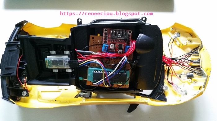
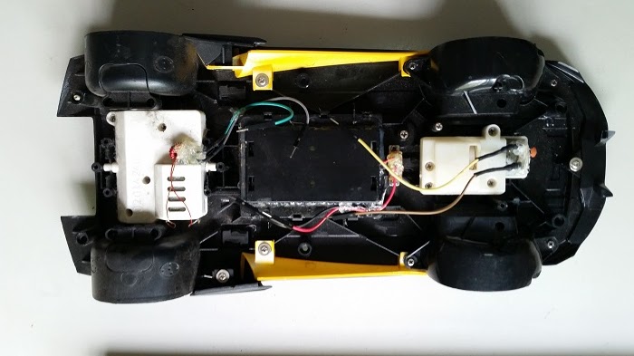
After buying this toy car I have replaced its RF circuit with the 8051 circuit. This toy car has two dc motors at its front and rear side. The front motor is used to control direction (left/right). And the rear motor is used to control the forward and backwards movement. A HC-06 Bluetooth module is used to receive command from android phone. A L298N H-bridge module allows you to control the speed and direction of two DC motors. A STC89C52RC microcontroller is used to control the whole system.
L298N H-bridge module
For more details about this module, please read here. I recommend you read it before you start.
Pin Description
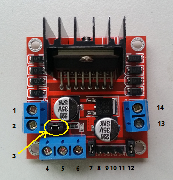
- Front DC motor "+"
- Front DC motor "-"
- 12V jumper - Leave this in place for this tutorial.
- Connect your motor supply voltage here and use between 7 and 12V DC to driver the motors for this tutorial.
- GND
- 5V output - If you're using between 7 and 12V DC to driver the motors and leave 12V jumper in place, the module can also supply your 8051 microcontroller with 5V DC.
- ENA - Front DC motor enable jumper. Leave this in place for this tutorial. If you want to control the speed of the front DC motor you must connect PWM output from your microcontroller to the ENA. For STC89C52RC, there is no PWM output. But you can use timer to implement PWM on 8051 if you want.
- IN1 - Direction of the front DC motor.
- IN2 - Direction of the front DC motor.
- IN3 - Direction of the rear DC motor.
- IN4 - Direction of the rear DC motor.
- ENB - Rear DC motor enable jumper. Leave this in place for this tutorial. If you want to control the speed of the rear DC motor you must connect PWM output from your microcontroller to the ENB. For STC89C52RC, there is no PWM output. But you can use timer to implement PWM on 8051 if you want.
- Rear DC motor "+"
- Rear DC motor "-"
Front motor truth table
| ENB | IN3 | IN4 | Description |
|---|---|---|---|
| 0 | N/A | N/A | Off |
| 1 | 0 | 0 | Stop |
| 1 | 0 | 1 | Anti-clockwise |
| 1 | 1 | 0 | Clockwise |
| 1 | 1 | 1 | Brake |
Rear motor truth table
| ENA | IN1 | IN2 | Description |
|---|---|---|---|
| 0 | N/A | N/A | Off |
| 1 | 0 | 0 | Stop |
| 1 | 0 | 1 | Anti-clockwise |
| 1 | 1 | 0 | Clockwise |
| 1 | 1 | 1 | Brake |
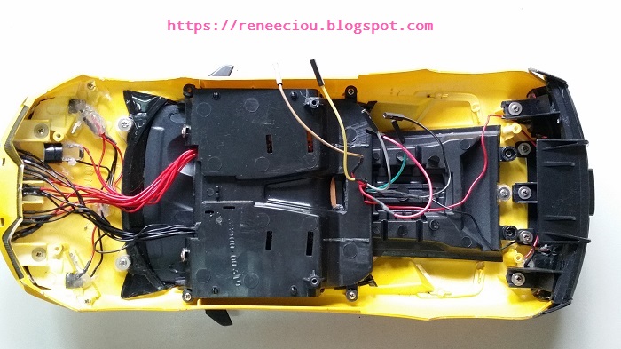
It is important to choose the right voltage for your power supply. Too low will result in reduced performance. Too high will cause damage to the motor. Make sure that the voltage does not exceed the voltage rating of your motors. For my toy car, I use two Panasonic NCR18650B 3.6 Volt 18650 batteries connected in series to supply approximately 7.2V. For your toy car, please choose the right voltage for your power supply. It depends on your motors.
Circuit Diagram
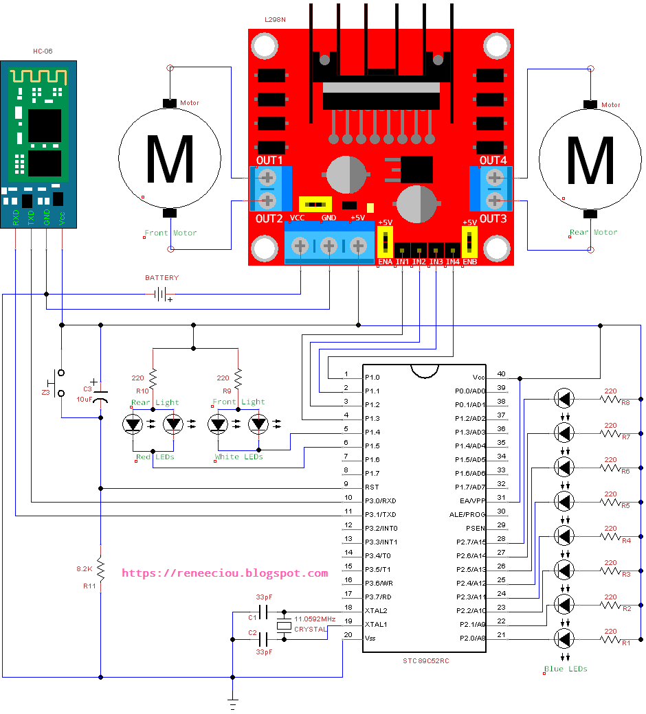
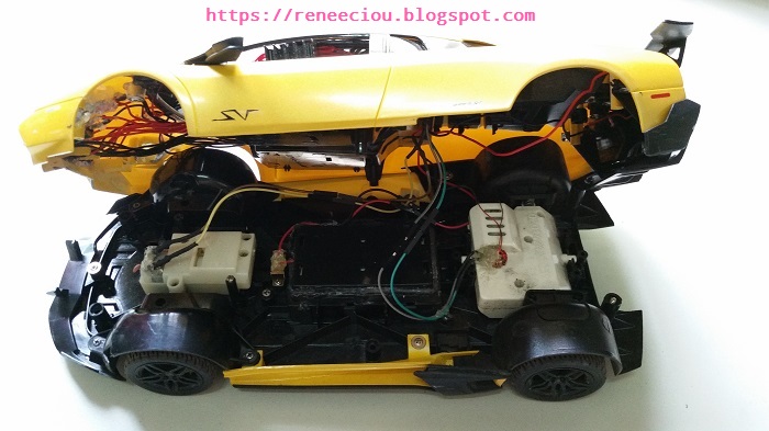
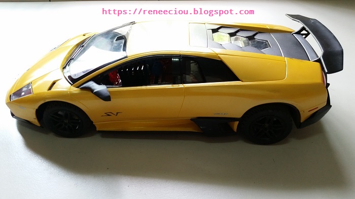
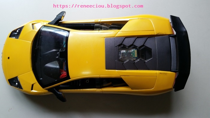
The following toy car is built by myself.
The following code is written in assembly language. You can rewrite it in C language. I think 8051 assembly language is not difficut. Its instruction set is not large so if you are a beginner, you can try to write programs in 8051 assembly language. There will be more understanding of 8051 microcontroller. But if code is more complex and large, and also consider the readability and portability, it is recommended to write code in C language. As for the 8051 development environment, you can refer to here.
Assembly Code
STOP    BIT     20H
TURN    BIT     21H
R_ON    BIT     22H
G_ON    BIT     23H
B_ON    BIT     24H
B_STP   BIT     25H
KP_MV   BIT     26H
        ORG     00H
        AJMP    START
        ORG     23H             ;Serial interrupt vector address
        AJMP    SERIAL_ROUTINE
        ORG     2BH             ;Timer2 interrupt vector address
        AJMP    TIMER2_ROUTINE
START:
        ACALL   INIT
        ACALL   INIT_SERIAL
        ACALL   INIT_TIMER2
LOOP:
        ACALL   DELAY
        JNB     B_ON, STOP_BLUE_LED
        JB      TURN, TURN_AROUND
        MOV     P2, A
        RL      A
        CJNE    A, #01111111B, SET_TURN_RIGHT
        SETB    TURN
        AJMP    LOOP
SET_TURN_RIGHT:
        AJMP    LOOP
TURN_AROUND:
        MOV     P2, A
        RR      A
        CJNE    A, #11111110B, SET_TURN_LEFT
        CLR     TURN
        AJMP    LOOP
SET_TURN_LEFT:
        AJMP    LOOP
STOP_BLUE_LED:
        JNB     B_STP, RESET_DONE
        CLR     B_STP
        MOV     A, #11111110B
        CLR     TURN
        MOV     P2, #255
RESET_DONE:
        AJMP    LOOP

;--------------------
; Delay
;--------------------
DELAY:  MOV     R6, #100
DLY1:   MOV     R7, #255
DLY2:   DJNZ    R7, DLY2
        DJNZ    R6, DLY1
        RET

;--------------------
; Initialize variables
;--------------------
INIT:
        MOV     SP, #60H
        CLR     STOP
        CLR     TURN
        CLR     R_ON
        CLR     G_ON
        CLR     B_ON
        CLR     B_STP
        MOV     A, #11111110B
        MOV     P0, #0
        MOV     P1, #00110000B
        MOV     P2, #255
        MOV     R5, #15
        RET

;--------------------
; Initialize serial
;
; TCON Register:
;  7   6   5   4   3   2   1   0
; TF1 TR1 TF0 TR0 IE1 IT1 IE0 IT0
;
; TMOD Register:
;   7     6    5   4    3     2    1   0
; GATE1 C/T1# M11 M01 GATE0 C/T0# M10 M00
;
; SCON Register:
;  7   6   5   4   3   2  1  0
; SM0 SM1 SM2 REN TB8 RB8 TI RI
;--------------------
INIT_SERIAL:
        MOV     SCON, #50H      ;Mode 1: 8-bit UART
        MOV     TMOD, #20H      ;Timer and reload mode
        MOV     TH1, #0FDH      ;Baud rate 9600bps
        MOV     TL0, #0FDH      ;Baud rate 9600bps
        SETB    TR1             ;Timer1 runs
        SETB    PS              ;High interrupt priority
        SETB    ES              ;Enable serial interrupt
        RET

;---------------------------------------------------
; Initialize timer2
;
; T2CON Register:
;  7   6    5    4     3    2   1     0
; TF2 EXF2 RCLK TCLK EXEN2 TR2 C/T2 CP/RL2
;
; 1 second = 11.0592MHZ / 12 = 921600 = 61440 * 15
; TH2 = (65536-61440)/256 = 16 = 10H
; TL2 = (65536-61440)%256 = 0 = 00H
;
; 0.5 second = 30720 * 15
; TH2 = (65536-30720)/256 = 136 = 88H
; TL2 = (65536-30720)%256 = 0 = 00H
;
; 0.25 second = 15360 * 15
; TH2 = (65536-15360)/256 = 196 = C4H
; TL2 = (65536-15360)%256 = 0 = 00H
;
; IE Register:
; 7  6  5  4   3    2   1   0
; EA - ET2 ES ET1  EX1 ET0 EX0
;---------------------------------------------------
INIT_TIMER2:
        CLR     EXF2            ;Reset flag
        CLR     TCLK            ;Disable baud rate generator
        CLR     RCLK            ;Disable baud rate generator
        CLR     EXEN2           ;Ignore events on T2EX
        MOV     TH2, #0C4H
        MOV     RCAP2H, #0C4H
        MOV     TL2, #00H
        MOV     RCAP2L, #00H
        CLR     CT2             ;Timer mode
        CLR     CPRL2           ;Reload mode
        CLR     PT2             ;Low interrupt priority
        SETB    ET2             ;Enable timer2 interrupt
        SETB    EA              ;Global interrupts enable
        SETB    TR2             ;Timer2 run
        RET

;-----------------------------------
; Timer2 interrupt service routine
;
; This is very important for the toy
; car to stop all actions when the
; bluetooth signal of your toy car
; is out of range, and no command
; is received after (0.25 * 2) second.
;
;-----------------------------------
TIMER2_ROUTINE:
        PUSH    ACC             ;Save ACC register on the stack
        DJNZ    R5, CONTINUE    ;Continue timer if it is less then 1 second
        JB      KP_MV, NO_CLEAR
        CLR     P1.0            ;Stop forward
        CLR     P1.1            ;Stop backward
        CLR     P1.2            ;Stop right
        CLR     P1.3            ;Stop left
NO_CLEAR:
        CLR     KP_MV
        MOV     R5, #15         ;Recount 0.25 second
CONTINUE:
        CLR     TF2             ;Reset interrupt flag
        POP     ACC             ;Restore ACC
        RETI

;----------------------------------------
; Serial port interrupt service routine
;----------------------------------------
SERIAL_ROUTINE:
        PUSH    ACC
        SETB    KP_MV
        MOV     A, SBUF
        JNB     A.5, RED_BUTTON
        SETB    STOP
        CLR     A.5
RED_BUTTON:
        CJNE    A, #01000001B, GREEN_BUTTON
        JB      STOP, STOP_RED_BUTTON
        SETB    R_ON
        LJMP    EXIT
STOP_RED_BUTTON:
        CLR     R_ON
        CLR     STOP
        LJMP    EXIT
GREEN_BUTTON:
        CJNE    A, #01000010B, BLUE_BUTTON
        JB      STOP, STOP_GREEN_BUTTON
        SETB    G_ON
        SJMP    EXIT
STOP_GREEN_BUTTON:
        CLR     G_ON
        CLR     STOP
        SJMP    EXIT
BLUE_BUTTON:
        CJNE    A, #01000011B, FORWARD
        JB      STOP, STOP_BLUE_BUTTON
        SETB    B_ON
        SJMP    EXIT
STOP_BLUE_BUTTON:
        CLR     B_ON
        CLR     STOP
        SETB    B_STP
        SJMP    EXIT
FORWARD:
        CJNE    A, #01000100B, BACKWARD
        JB      STOP, STOP_FORWARD
        SETB    P1.0
        SJMP    EXIT
STOP_FORWARD:
        CLR     P1.0
        CLR     STOP
        SJMP    EXIT
BACKWARD:
        CJNE    A, #01000101B, RIGHT
        JB      STOP, STOP_BACKWARD
        SETB    P1.1
        SJMP    EXIT
STOP_BACKWARD:
        CLR     P1.1
        CLR     STOP
        SJMP    EXIT
RIGHT:
        CJNE    A, #01000110B, LEFT
        JB      STOP, STOP_RIGHT
        SETB    P1.2
        SJMP    EXIT
STOP_RIGHT:
        CLR     P1.2
        CLR     STOP
        SJMP    EXIT
LEFT:
        CJNE    A, #01000111B, CAR_FRONT_LIGHT
        JB      STOP, STOP_LEFT
        SETB    P1.3
        SJMP    EXIT
STOP_LEFT:
        CLR     P1.3
        CLR     STOP
        SJMP    EXIT
CAR_FRONT_LIGHT:
        CJNE    A, #01001000B, CAR_REAR_LIGHT
        JB      STOP, STOP_FRONT_LIGHT
        CLR     P1.4
        SJMP    EXIT
STOP_FRONT_LIGHT:
        SETB    P1.4
        CLR     STOP
        SJMP    EXIT
CAR_REAR_LIGHT:
        CJNE    A, #01001001B, EXIT
        JB      STOP, STOP_REAR_LIGHT
        CLR     P1.5
        SJMP    EXIT
STOP_REAR_LIGHT:
        SETB    P1.5
        CLR     STOP
EXIT:
        CLR     RI
        POP     ACC
        RETI
        END
Demo
Warning and disclaimer:
If you don't have any basic electronics knowledge, please don't try this one. The author takes no responsibility for any damages caused as a result of this tutorial. Try this one at your own risk.
沒有留言:
不接受新意見。