Warning and disclaimer:
If you don't have any basic electronics knowledge, please don't try this one. The author takes no responsibility for any damages caused as a result of this tutorial. Try this one at your own risk.
I am going to use a STC89C52RC microcontroller with a HC-06 UART interface Bluetooth module to create a Bluetooth remote shutter. The remote shutter is intended for use with Bluetooth Remote Toy, which is an android based application developed by me and can be downloaded form Google play store.
When the app is connected to the remote shutter, it will send the identification command 'W' to the remote shutter. When the remote shutter receives this command, it must return its ID 'I' to the app. Otherwise the app will think that the remote device is the camera shutter, which is a part of the app, not your own DIY remote shutter. The camera initialization is not the same for the remote shutter and the camera shutter.
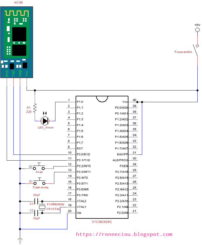
The circuit diagram is as follows. When the Z0 Snap button is pressed, a byte 'T' character is sent to the app, and the green LED will start flashing. When the app received 'T' character, it will start taking a picture. After finished taking a picture, the app will return a byte 'D' character to the remote shutter. If the remote shutter receives a 'D' character, the LED will stop blinking. If the remote shutter does not receive the 'D' character, the 10 seconds timeout will stop flashing.
When the Z1 Flash mode button is pressed, a byte 'M' character is sent to the app. The app will change the flash mode to next when it receives the 'M' character. You can also consider using other MCUs, like Arduino and so on.
Circuit Diagram
In circuit diagram there are two buttons, one for snap and another for flash mode. A LED is used to indicate taking a picture. A HC-06 Bluetooth module is used to receive/transmit command from/to android phone. A STC89C52RC microcontrolleri used to control the whole system.
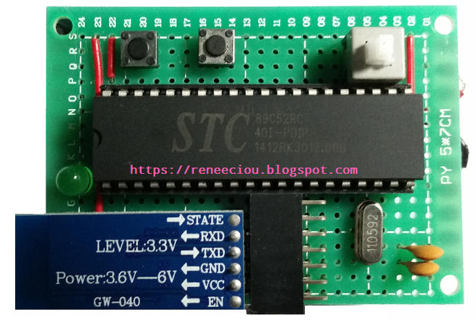
The following remote shutter is built by myself.
The following code is written in assembly language. You can rewrite it in C language. I think 8051 assembly language is not difficut. Its instruction set is not large so if you are a beginner, you can try to write programs in 8051 assembly language. There will be more understanding of 8051 microcontroller . But if code is more complex and large, and also consider the readability and portability, it is recommended to write code in C language. As for the 8051 development environment, you can refer to here.
Assembly Code
COUNT   EQU     30H
SNAP    BIT     20H
        ORG     00H
        AJMP    START
        ORG     03H             ;Int0 interrupt vector address
        AJMP    INT0_ROUTINE
        ORG     13H             ;Int1 interrupt vector address
        AJMP    INT1_ROUTINE
        ORG     23H             ;Serial interrupt vector address
        AJMP    SERIAL_ROUTINE
        ORG     2BH             ;Timer2 interrupt vector address
        AJMP    TIMER2_ROUTINE
START:
        ACALL   INIT
        ACALL   INIT_INT0
        ACALL   INIT_INT1
        ACALL   INIT_SERIAL
        ACALL   INIT_TIMER2
LOOP:
        ACALL   DELAY
        JNB     SNAP, NO_FLASH
        JNB     P1.0, LED_OFF
        CLR     P1.0
        AJMP    LOOP
LED_OFF:
        SETB    P1.0
NO_FLASH:
        AJMP    LOOP

;--------------------
; Delay
;--------------------
DELAY:  MOV     R6, #255
DLY1:   MOV     R7, #255
DLY2:   DJNZ    R7, DLY2
        DJNZ    R6, DLY1
        RET

;--------------------
; Initialize variables
;--------------------
INIT:
        MOV     SP, #60H
        MOV     P1, #11111110B
        MOV     R5, #15
        MOV     COUNT, #0
        CLR     SNAP
        RET

;--------------------
; Initialize int0
;--------------------
INIT_INT0:
        SETB    IT0             ;edge triggered
        SETB    EX0             ;Enable int0 interrupt
        SETB    PX0             ;High interrupt priority
        RET

;--------------------
; Initialize int1
;--------------------
INIT_INT1:
        SETB    IT1             ;edge triggered
        SETB    EX1             ;Enable int0 interrupt
        SETB    PX1             ;High interrupt priority
        RET

;--------------------
; Initialize serial
;
; TCON Register:
;  7   6   5   4   3   2   1   0
; TF1 TR1 TF0 TR0 IE1 IT1 IE0 IT0
;
; TMOD Register:
;   7     6    5   4    3     2    1   0
; GATE1 C/T1# M11 M01 GATE0 C/T0# M10 M00
;
; SCON Register:
;  7   6   5   4   3   2  1  0
; SM0 SM1 SM2 REN TB8 RB8 TI RI
;--------------------
INIT_SERIAL:
        MOV     SCON, #50H      ;Mode 1: 8-bit UART
        MOV     TMOD, #20H      ;Timer and reload mode
        MOV     TH1, #0FDH      ;Baud rate 9600bps
        MOV     TL0, #0FDH      ;Baud rate 9600bps
        SETB    PS              ;High interrupt priority
        SETB    ES              ;Enable serial interrupt
        SETB    TR1             ;Timer1 runs
        RET

;---------------------------------------------------
; Initialize timer2
;
; T2CON Register:
;  7   6    5    4     3    2   1     0
; TF2 EXF2 RCLK TCLK EXEN2 TR2 C/T2 CP/RL2
;
; 1 second = 11.0592MHZ / 12 = 921600 = 61440 * 15
; TH2 = (65536-61440)/256 = 16 = 10H
; TL2 = (65536-61440)%256 = 0 = 00H
;
; IE Register:
; 7  6  5  4   3    2   1   0
; EA - ET2 ES ET1  EX1 ET0 EX0
;---------------------------------------------------
INIT_TIMER2:
        CLR     EXF2            ;Reset flag
        CLR     TCLK            ;Disable baud rate generator
        CLR     RCLK            ;Disable baud rate generator
        CLR     EXEN2           ;Ignore events on T2EX
        MOV     TH2, #10H
        MOV     RCAP2H, #10H
        MOV     TL2, #00H
        MOV     RCAP2L, #00H
        CLR     CT2             ;Timer mode
        CLR     CPRL2           ;Auto-reload mode
        CLR     PT2             ;Low interrupt priority
        SETB    ET2             ;Enable timer2 interrupt
        SETB    EA              ;Global interrupts enable
        SETB    TR2             ;Timer2 run
        RET

;---------------------------------
; Snap timeout
;---------------------------------
START_SNAP_TIMEOUT:
        JNB     SNAP, NO_COUNT
        MOV     A, COUNT
        INC     A               ;10 seconds timeout for snapping
        MOV     COUNT, A
        CJNE    A, #10, NO_COUNT
        CLR     SNAP
        MOV     COUNT, #0
        CLR     P1.0
NO_COUNT:
        RET

;---------------------------------
; Int0 interrupt service routine
;---------------------------------
INT0_ROUTINE:
        JB      SNAP, IGNORE_SNAP
        SETB    SNAP            ;Indicate that we are taking a picture
        MOV     COUNT, #0
        MOV     SBUF, #84       ;Send value 84('T') to serial port
        JNB     TI, $           ;Pause until the TI bit is set
IGNORE_SNAP:
        RETI

;---------------------------------
; Int1 interrupt service routine
;---------------------------------
INT1_ROUTINE:
        MOV     SBUF, #77       ;Send value 77('M') to serial port
        JNB     TI, $           ;Pause until the TI bit is set
        RETI

;-----------------------------------
; Timer2 interrupt service routine
;-----------------------------------
TIMER2_ROUTINE:
        PUSH    ACC             ;Save ACC register on the stack
        DJNZ    R5, CONTINUE    ;Continue timer if it is less then 1 second
        ACALL   START_SNAP_TIMEOUT
        MOV     R5, #15         ;Recount 1 second
CONTINUE:
        CLR     TF2             ;Reset interrupt flag
        POP     ACC             ;Restore ACC
        RETI

;----------------------------------------
; Serial port interrupt service routine
;----------------------------------------
SERIAL_ROUTINE:
        PUSH    ACC
        JB      TI, IGNORE
        MOV     A, SBUF
        CJNE    A, #68, ID_CHK  ;Receive vlaue 68('D') from serial port
        CLR     SNAP
        MOV     COUNT, #0
        CLR     P1.0
ID_CHK:
        CJNE    A, #87, IGNORE  ;Receive vlaue 87('W') from serial port
        MOV     SBUF, #73       ;Send value 73('I') to serial port
        JNB     TI, $           ;Pause until the TI bit is set
        JMP     NO_CLEAR_TI
IGNORE:
        CLR     TI
NO_CLEAR_TI:
        CLR     RI
        POP     ACC
        RETI
        END
Demo
Warning and disclaimer:
If you don't have any basic electronics knowledge, please don't try this one. The author takes no responsibility for any damages caused as a result of this tutorial. Try this one at your own risk.
沒有留言:
不接受新意見。